- GENERIC STANDARD
- SAMPLE DOCUMENTS
Pitfalls of Electromagnetic Shielding
When metal shielding is added in order to reduce EM emissions from the electronic equipment, most people expect the radiated emissions to go down. However, this is not always the case, as sometimes emissions may rise. While this seems counterintuitive, it does happen, and because of this, design engineers often think that EMC/EMI is difficult. However, there are explainable and fixable reasons for this, and we will explain them in this section.
The first possible explanation is that design engineers often forget to think about noise (unwanted electromagnetic energy), they instead focus on signals and their corresponding circuits. A simple thing to remember is that the electrical energy (or signal) in any circuit, when sent from point A to point B within the circuit, is not traveling in the electrical conduct. Most of this energy actually exists in the space surrounding the conductor.
You would not see an equation for the energy within the conductor, or in terms of the resistance of the conductor. Equations for energy or power with regards to resistance, defines the amount of energy wasted and is given by the current squared multiplied by the resistance I2xR. Any equation regarding stored energy is determined by capacitor or inductor because the energy within a circuit is stored in the capacitors and inductors. So, the amount of energy stored in an inductor at any given time is given by the equation 1/2LI2. Similarly, the energy stored in a capacitor is given by 1/2CV2. The capacitance and inductance are related to the physical space around the conductor and not its resistance (or conductance). So really, the energy exists in the space surrounding the conductor and, depending on the frequency of the signal, some of this energy could radiate out or couple to other circuits. Therefore, the conductor that is supposed to carry the signal (energy) from any point A to point B could lose this energy to any conductor or circuit in the vicinity. This phenomenon is generally described as crosstalk (from one circuit to the other). Basically, that is electromagnetic noise because this energy is going where it is not needed.
Another way of looking at this is that the energy escaping or radiating from one circuit, is picked up by another circuit. The source circuit could also radiate this energy completely outside the system, where it could then be picked up by another system close by.
In order to reduce the electromagnetic noise escaping the equipment, a design engineer may attempt to contain this energy within the system by enclosing the equipment in a metal enclosure or shield. In this situation the enclosure, sometimes referred to as a Faraday cage, contains the escaping energy within. However, not all enclosures are ideal Faraday Cages in the sense that they have imperfections.
Effects of EMI
Depending on the affected systems and the type of EMI, the results of unwanted EMI can range from simple nuisance to disastrous. EMI can cause interference in somewhat benign ways on televisions, ATMs and radios, or in more serious ways on aeronautical communication systems, cardiac pacemakers or other vital electronic and electrical devices.
The main concept behind EMC compliance is that devices should perform as expected within their given environment, without impeding on other devices around them, or sacrificing their own performance due to unwanted EMI.
These imperfections are:
-
 Openings
 - Conductors going in or out and
- Finite thickness of the shield
Now, let’s look at the three weaknesses of the Faraday cage listed above one by one.
First, as seen in Figure 1 below, the openings allow the electromagnetic energy to leak out. Such openings take the form of (a) seams, which may not be visible or (b) slots. We have to minimize the leakage through these openings.
Second, the conductors going in or out may be signal cables, power cables, or simply ground conductors. These items can pick up the energy from inside the enclosure, carry it through the metal walls, and radiate it outside the enclosure. We also have to minimize the energy these cables and conductors are able to pick up from one side and radiate to the other side. This can be done by appropriate application of cable shielding and filtering.
Third and final consideration is the wall thickness. Depending on the frequency of the electromagnetic energy, the thickness of the metal enclosure only provides limited amounts of shielding because the shielding provided by the metal is dependent on the thickness, conductivity, and permeability of the enclosure. The inside surface of the metal reflects the energy, keeping it inside the enclosure. However, part of this energy is absorbed by the metal as it travels towards the outside of the enclosure.
Note: As we will discuss later, the energy absorbed by the metal is the main advantage of using a Faraday Cage because this electromagnetic energy converts to heat.
NOISE PROPAGATION
SYSTEM ENCLOSURE = A RESONANT CAVITY
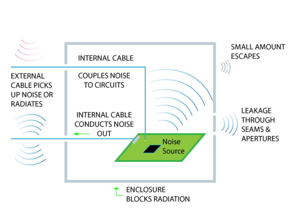
Figure 1: A Faraday Cage or enclosure shows how openings, cable conductors, and metal thickness may lead to energy leaking out.
The electromagnetic energy contained within the enclosure (or the Faraday cage) bounces back and forth between the metal walls. Some of the energy escapes the enclosure by the three limitations described above. But some of the energy is also absorbed by the metal within its thickness. The circuits produce RF energy continuously with clocks and data to perform its control/ computing/ communication function. Ideally, this energy may be absorbed in the circuit but some escapes. The energy escaping the circuit may remain within the enclosure or escape by the three methods. Initially, the energy level inside the Faraday cage rises, however, it cannot rise indefinitely, because that would also increase the energy escaping by each of the three methods. So, equilibrium is reached very quickly when the energy produced by the circuit equals the energy escaping the enclosure. Then the energy levels inside the enclosure reach a steady level. This steady state level (within the enclosure) is generally much higher than it would be if the enclosure was not present. Also, some of the energy leaked by the openings or re-radiated by the cables may be directed towards the antenna used for emissions measurement and possibly more concentrated in some directions. This explains why the energy levels may be higher with the use of the enclosure than without it. Therefore, if you’re the design engineer and you’re told that the emissions levels increased with the enclosure, you might consider that inaccurate or unbelievable.
We still use the enclosure to suppress noise escaping the EUT. Analyzing this situation, helps us realize that reducing the noise optimizes the phenomenon that absorbs the energy within the materials (metal) of the enclosure. As previously mentioned, this material absorbs the electromagnetic energy and converts it into heat. Thus, the net energy escaping the enclosure is equal to the energy radiated by the circuit minus the energy absorbed by the Faraday cage.
To conclude, the real advantage of the Faraday cage, is that the enclosure acts as a sink for the electromagnetic energy by converting it into heat.